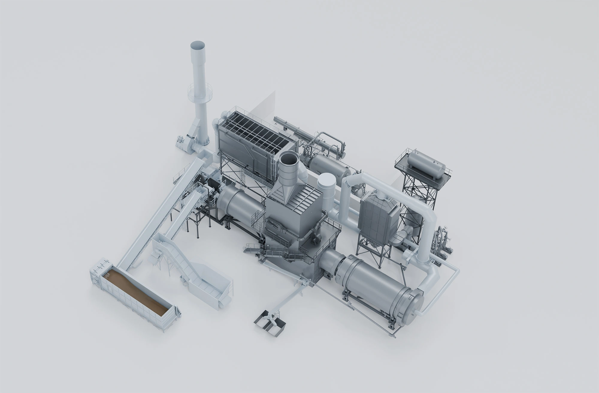
Six configurations that recover energy from waste, biomass and hazardous fractions on your own site. Engineering, design, manufacturing and financing, all in-house.
Thermal efficiency that turns into energy profitability.
Smart waste, profit energy·From waste to resource·Smart waste, profit energy·from waste to resource·Smart waste, profit energy·from waste to resource·Smart waste, profit energy·from waste to resource·
Why Waste to Energy?
Waste stops being a management cost
A TVE plant works on three lines of your P&L at once: what you pay to get the waste out, what you pay for energy, and what you can charge to treat someone else's.
01
You stop paying for landfill
Every tonne you recover on site is a tonne that stops paying transport, levy and landfill. It is the line on your invoice that only goes up as European regulation tightens.
02
You stop buying gas and power
The heat, steam and power you produce displace natural gas and grid electricity in your own process. Your energy bill stops depending on a market you do not control.
03
You start charging for other people's waste
The gate fee you charge for third-party waste, and any surplus power exported to the grid, turn a treatment cost into an asset with its own revenue line.
And with the same project, the environmental file
Diversion of non-recyclable fractions away from landfill
Decarbonisation of scope 1 and 2 emissions in your own process
ESG eligibility and access to green financing when the fuel is biogenic
How we do it
Three phases, one single point of responsibility
We design, manufacture and commission the three phases in our own production centres. There is no need to integrate three suppliers, and no guarantee to argue over when something fails.
Inputs— what the plant receives
Input AWaste-derived fuels
RDF · CSR
Green RDF · compost oversize · biostabilised
Non-recyclable fractions — a high calorific value is not required
Raw MSW does not enter a grate: it is fed as RDF or SRF
Input BBiomass & organics
Agro-industrial and forest biomass
Wood and paper residues
WWTP sludge — up to 50% moisture
Up to 30% ash content
Input CHazardous waste
Chemical and pharmaceutical waste
Heterogeneous SRF · complex mixes
Industrial sludge with contaminants
Dir. 2010/75/EU · high gate fees
TVE process — 3 phases
The process— three sequential phases
Phase 1Combustion or oxidation
The fuel is thermally broken down on a grate or in a rotary kiln. This is where the temperature, residence time and emissions control required by your permit are set.
SGC — Moving step grate
USC — Underfeed stoker
RKC — Rotary kiln + afterburner chamber
Oxidation chamber when strict CO control is required
Phase 2Heat transfer
The hot gases hand their energy over to a working fluid in the boiler: thermal oil, steam or water. The choice of fluid decides which energy leaves the plant and how the boiler is protected.
HZB Horizon+ · rotary thermal-oil boiler
SPB · saturated or superheated steam, up to 40 bar / 400 °C
TOB · vertical thermal-oil boiler
HWB · hot or superheated water
TREN hybrid · thermal oil producing clean steam for the turbine
Phase 3Power generation
The working fluid drives a turbine coupled to a generator. It is an optional phase: when the project only needs heat, the plant stops at phase 2.
ORC · Organic Rankine Cycle
Steam turbine
N.A. · thermal only, no power block
Scale alone no longer sets the boundary: steam turbines are now competitive below 2 MWe
Energy outputs
Outputs— monetisable energy
Output 1Electricity
0,5 – 10+ MWe
Industrial self-supply
Grid export
Output 2Process steam
Saturated or superheated steam
Up to 40 bar / 400 °C
Direct extractions into your process
Output 3Thermal heat
Hot thermal oil
Hot or superheated process water
Hot flue gases, direct — no boiler in this configuration
Output 4Cogeneration
Power and heat simultaneously
Recovers residual heat at 150–180 °C
Rarely ruled out in full by local regulation
ATEX. Every thermal-fluid installation — the HTF circuit that carries the heat — is designed under the ATEX framework, the European explosive-atmospheres regulation, whatever the configuration, including thermal-only plants. We fit it to how demanding your own site is.
How we prescribe
We prescribe on evidence, not from a catalogue
Before we propose a configuration we settle two decisions, in this order: which thermal process your fuel and your permit allow, and which working fluid makes the most of that choice. There are four possible routes, and each has its own ground. We show you all four and explain which one fits your case best, and why.
Level 1Thermal process — decided by your emissions permit and by the characteristics of your fuel
Level 2Working fluid — decided by which energy it pays you to produce
Route A.1Steam cycle
High viability: less entrained ash makes the steam cycle technically feasible.
What it brings
The highest electrical efficiencies in the range
Mature technology, with decades of operation on the market and full supplier freedom
Where it fits best
Projects focused on net electrical output, with clean and stable fuel
The superheater is protected with Inconel — a nickel superalloy against corrosion — which the technical study sizes for your fuel
Local CO regulationAsh load and acid attackCogeneration requirementORC turbine supply and competitivenessCalorific value (LHV) and corrosivity of the fuel
On a small plant, when we refine the route
If combustion plus HTF/ORC is on the table, oxidation plus steam cycle gains ground when any of these apply: strict local CO limits (France, for instance), an exclusive requirement for net electrical output without cogeneration, or an ORC turbine supply context that favours another route.
In practice cogeneration is almost never ruled out in full by local rules: residual heat at 150–180 °C is still recoverable.
On a large plant, when we refine the route
If oxidation plus steam cycle is on the table, combustion plus HTF brings more when there are highly corrosive critical fuels, a regulatory framework that does not require an oxidation stage, or when your priority is thermal demand, that is, high-enthalpy industrial cogeneration.
The TREN scheme works equally well on small and large projects whenever combustion has been chosen.
Every prescription closes by characterising your actual fuel in our own laboratory, not a textbook fuel.
We order them by what actually decides the project: the fuel going in, and the energy you need coming out. They do not compete with each other: each one is designed for specific conditions, and all of them are tailored to the actual scope of your installation. Three of them are SWIP — Small Waste Incineration Plant, the regulatory category for a decentralised plant.
Thermal only
TVE-T
ThermoValue THERMAL
Process heat from waste-derived fuel. No power block.
Fuel
RDF · SRF · derived
Range
0,5 – 25 MWt
Phase 1
SGC · USC
Phase 2
HZB · SPB · TOB · HWB
The most direct configuration in the range: from waste to process heat in two phases
No turbine and no power cycle: simpler permitting and operation
Four thermal output formats to match your process
Design keys
Ready to grow: if you expect to generate power in the future, we design for it from day one so the plant is ready to take the power block when the time comes.
If your case is different
If your fuel is clean biomass rather than waste, look at TVE-4: the same platform, sized for biogenic fuel.
Ideal scale: Any size up to 25 MWt — multi-unit above
SWIP · ORC
TVE-1
ThermoValue SWIP-ORC
Thermal oil and ORC cycle. Maximum reliability on dirty, variable fuel.
Fuel
RDF · SRF · organics
Range
0,5 – 2 MWe
Phase 2
HZB Horizon+ · patent
Efficiency*
18,5 – 20,2%
Unpressurised oil circuit: the boiler runs clean and free of corrosion
First choice for cogeneration and high-ash fuels, whatever the plant size
Horizon+ is our own patent, and the ORC turbine comes under an exclusive supply agreement
Design keys
It needs no certified steam-boiler operator. Like any industrial plant, it has a plant operator.
Each Horizon+ unit has a defined nominal power: above it the plant is configured as multi-unit, with footprint and maintenance sized in the technical study.
If your case is different
If the fuel is clean and stable and you want maximum electrical yield above 3 MWe, look at TVE-2.
Ideal scale: Optimal below 2 MWe — and at any power when ash or cogeneration decide
SWIP · Steam
TVE-2
ThermoValue SWIP-VAPOR
Direct steam cycle. The highest electrical efficiency in the portfolio.
Fuel
RDF · SRF · low ash
Range
2 – 10+ MWe
Phase 2
SPB · 40 bar / 400 °C
Efficiency*
18,1 – 23,8%
The highest electrical efficiencies in the range
Mature technology and full supplier freedom — no single-vendor lock-in
At large scale it delivers its full potential: cycle and materials sized to produce electricity continuously
Design keys
It performs at its best with a stable, continuous load regime: this is the configuration designed to produce electricity all year round.
With higher-ash fuels the superheater is protected with Inconel, a nickel superalloy that the technical study sizes for your case.
If your case is different
If your waste supply is seasonal or the fuel carries a lot of ash, look at TVE-1 or TVE-3: thermal fluid is designed for those conditions.
Ideal scale: Optimal above 3 MWe with low ash load
SWIP · TREN
TVE-3
ThermoValue SWIP-TREN
Thermal-oil boiler feeding a clean steam train. Oil reliability with steam efficiency.
Fuel
RDF · SRF · high ash
Range
1 – 10+ MWe
Phase 2
TREN: HZB + steam producer
Efficiency*
16,6 – 21,8%
Cogeneration with steam, designed to measure with direct extractions
High ash and acid attack: the risk moves to a clean external exchanger
Conventional steam turbine: full independence from the ORC turbine supplier
Design keys
It integrates two fluid circuits, thermal oil and steam, into a single system: water treatment is a small fraction of the steam produced.
It is the most recent configuration in the range: it combines the Horizon+ boiler, with years of operation behind it, and the steam cycle, which has been on the market for decades.
If your case is different
If your fuel is clean, the load is stable and you only want electrical yield, look at the direct steam cycle of TVE-2.
Ideal scale: Small and large alike, wherever combustion has been chosen
BIO · Biomass
TVE-4
ThermoValue BIO
Clean biomass and sludge. The same platform as TVE-T, sized for biogenic fuel.
Fuel
Biomass · WWTP sludge
Range
0,5 – 25 MWt
Moisture
Up to 50%
Ash
Up to 30%
It shares its mechanical platform with TVE-T — a grate proven on waste — and is sized specifically for biomass
Renewable energy: ESG eligibility and access to green financing
Our own know-how in biomass combustion, manufactured in our centres in Spain, Turkey and Brazil
Design keys
Above 50% moisture we add a drying stage before the grate, integrated into the plant design.
The usual boiler is TOB, SPB or HWB; Horizon+ is reserved for very particular biomass.
If your case is different
If what you recover is waste rather than biomass, look at TVE-T, with equipment built for a more demanding stream.
Ideal scale: Any size up to 25 MWt — multi-unit above
HAZ · Hazardous
TVE-5
ThermoValue HAZ
Hazardous and heterogeneous waste. Rotary kiln with afterburner chamber.
Fuel
Hazardous · mixed SRF
Range
0,5 – 5+ MWe
Phase 1
RKC + afterburner
Burnout
> 99,9%
The configuration in the portfolio for hazardous, heterogeneous mixes
The gate fee on hazardous waste gives the project a solid, predictable revenue line
Highly bankable: a stable waste contract lowers the financial risk
Design keys
Designed for Directive 2010/75/EU: at least 850 °C for 2 s, and at least 1,100 °C for 2 s above 1% halogenated organics expressed as chlorine. The kiln and the permitting process are planned around those parameters from the outset.
Kiln capacity is sized project by project, against your actual waste mix.
If your case is different
If the waste is neither hazardous nor heterogeneous, the grate configurations (TVE-T to TVE-3) are designed for your stream.
Ideal scale: Optimal above 1 MWe
Six starting configurations, one that fits your project best and, often, alternatives that also work. We tell you which and why: every Bianna solution adapts to the real needs of your project, your sector and your client.
* Overall efficiency. Nominal theoretical values under ideal isolated conditions, not project measurements. Real performance depends on the load regime, on the fuel LHV and on the cogeneration scheme.
Side by side
The same table we prescribe with
The technical criteria that actually guide the decision, side by side. There is no better configuration: there is one that fits your fuel, your energy output and your site best. This table lets you see it at a glance.
Configuration
Fuel
Phase 1
Phase 2
Phase 3
Range
Efficiency*
Ash load
When we choose it
TVE-TTHERMAL
RDF · SRF · derived
SGC · USC
HZB · SPB · TOB · HWB
N.A.
0,5–25 MWt
N.A. — thermal output
Medium–high
Process heat only, any size
TVE-1SWIP-ORC
RDF · SRF · organics
SGC
HZB Horizon+
ORC
0,5–2 MWe
18,5 – 20,2%
High
High ash or cogeneration, at any power
TVE-2SWIP-VAPOR
RDF · SRF · low ash
SGC + oxidation
SPB 40 bar / 400 °C
Steam turbine
2–10+ MWe
18,1 – 23,8%
Low and homogeneous
Above 3 MWe with low ash and a stable load
TVE-3SWIP-TREN
RDF · SRF · high ash
SGC
TREN: HZB + steam producer
Steam turbine
1–10+ MWe
16,6 – 21,8%
High
High ash at any scale, with a conventional steam turbine
TVE-4BIO
Biomass · sludge
SGC · USC
TOB · SPB · HWB
N.A. or ORC / steam
0,5–25 MWt
Depends on the power block
Up to 30%
Clean biomass fuel, any size
TVE-5HAZ
Hazardous · mixed SRF
RKC + afterburner
SPB · HZB
ORC or steam turbine
0,5–5+ MWe
Depends on configuration
High and heterogeneous
Hazardous or heterogeneous waste
Swipe sideways to see the full table.
Ash load is the criterion that most often guides the choice ahead of scale: a high-ash, acid-attacking fuel finds its natural ground in the thermal fluid of TVE-1 or TVE-3, whatever the plant size.
Is this your case?
Find your case
Every profile arrives with a different problem. These are the four we see most, and the configurations that solve them.
Councils · Associations · Public waste companies
Municipal & public
What they tell us
Rising landfill cost and European regulatory pressure on buried waste
Need for municipal energy self-sufficiency and a lower energy bill
Hard to secure bankable financing without a stable waste contract
Maximum availability with limited maintenance resources
Raw MSW does not enter the plant as it is: it needs upstream preparation into RDF or SRF, which we also engineer
Know which configuration fits you before you talk to anyone
Six questions. We return the thermal process, the working fluid and the TVE configuration that fits best — together with the alternative that can also work — using the same criteria we apply in an engineering study.
1
Fuel
2
Output
3
Scale
4
CO limits
5
Ash
6
Priority
What is the nature of the fuel?
Waste and biomass deserve independent solutions: each stream has its own platform, sized to measure.
What energy output do you need?
Cogeneration is rarely ruled out in full: residual heat at 150–180 °C is still recoverable.
What is the scale of the project?
Approximate target output. Scale refines the choice; it does not decide it on its own.
How strict is CO and emissions regulation at the site?
This is the first-level question: it decides between oxidation and conventional combustion.
What ash load and chemical aggressiveness does the fuel have?
This is the criterion that most often guides the final choice ahead of scale.
What is the main priority of the project?
The last input: it guides the choice when two routes remain technically valid.
Indicative results, subject to a final study that determines the technical configuration, the scope and the economic proposal. Get in touch with us.
Why Bianna?
The Bianna experience
We are a multinational specialising in the engineering, design, manufacturing and financing of advanced technology for the management, treatment and recovery of waste. The plant we prescribe is the plant we build, commission and maintain.
+35
Years of experience
+1,100
Projects and references
6
Sites
+86,500
m² of own production capacity
+30
Countries
Headquartered in Celrà (Girona) and present internationally, Bianna has 6 sites and more than 86,500 m² of its own production capacity across centres in Spain, Turkey and Brazil, with a commercial presence in more than 30 countries.
We also finance. The renting models of BRS, Bianna Renting Services, let you take on the project without tying up resources from day one, and clear the barrier that stops many Waste to Energy projects before the engineering even starts.
La gestión sostenible del residuo será rentable o no será
Bianna Recycling, S.L.U.
Next step
Request a personalised technical study
Our engineering team studies your case and returns a preliminary proposal with the prescribed configuration, the energy balance and the scope of supply for your project.
Engineering, supply, integration and commissioning. One single point of contact for the whole project cycle.
Celrà (Girona) · engineering, manufacturing and commissioning under one roof
In-house manufacturing and proprietary technology, delivered turnkey (EPC)
BRS renting models: our own financing route for your project
Bianna Recycling, S.L.U. · TVS — Thermo Value Solutions
Tell us about your project
Fuel type, approximate volume, location, energy needs and CO requirements at the site. That is all we need to start. We will take it from Bianna's contact page.