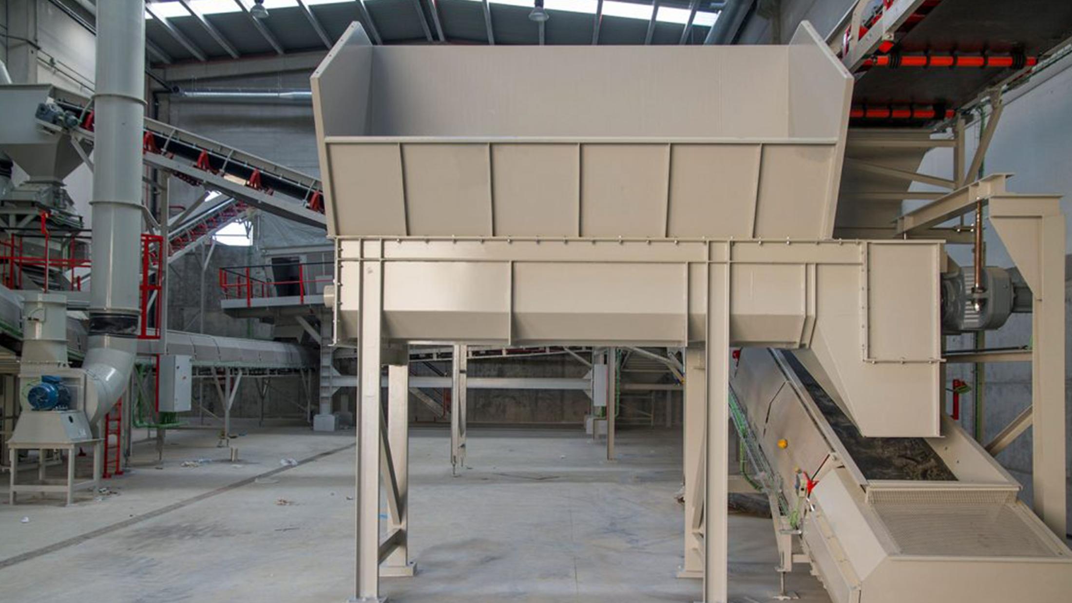
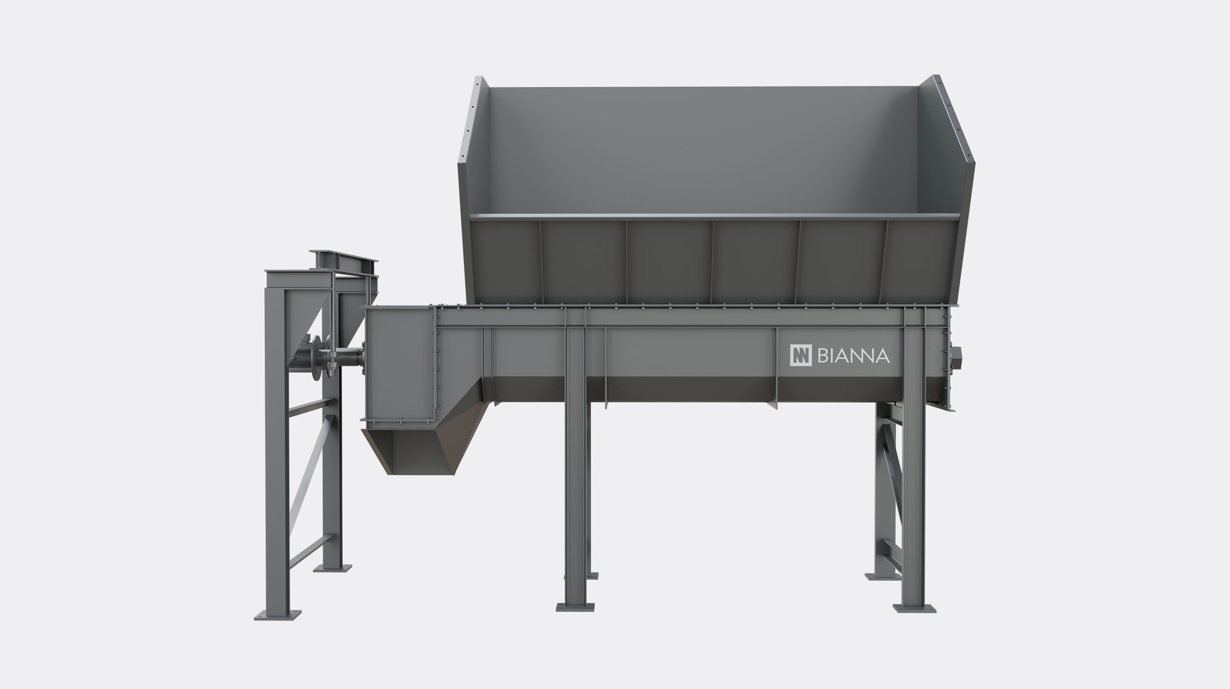
SF Screw Feeder
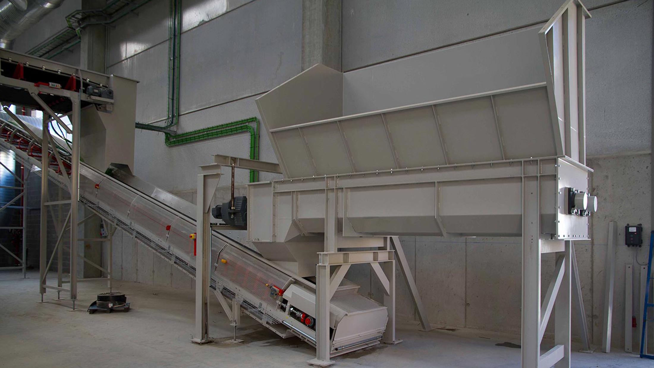
Bianna Screw Feeders are designed to ensure continuous, stable and perfectly metered feeding of the material to be treated. They are the ideal starting point for lines that process bulk, dense or wet materials, ensuring that downstream mechanical equipment always operates at its optimal performance point and without overloads.
Enables uniform and steady feeding in compost refining lines.
Perfect Metering
Ensures a constant and regulated material flow, radically optimizing and improving the efficiency of downstream mechanical separation.
High Strength and Stability
Heavy-duty, compact structure engineered to withstand continuous massive loads in its hopper without deformation.
Combined Action (2 in 1)
In versions equipped with rotating paddles, the equipment not only meters and conveys, but also performs rigorous breaking, mixing and homogenization.
Custom Adaptability
Both the receiving hopper and the discharge hopper are custom-designed to meet the geometric, inclination and flow requirements of each project.
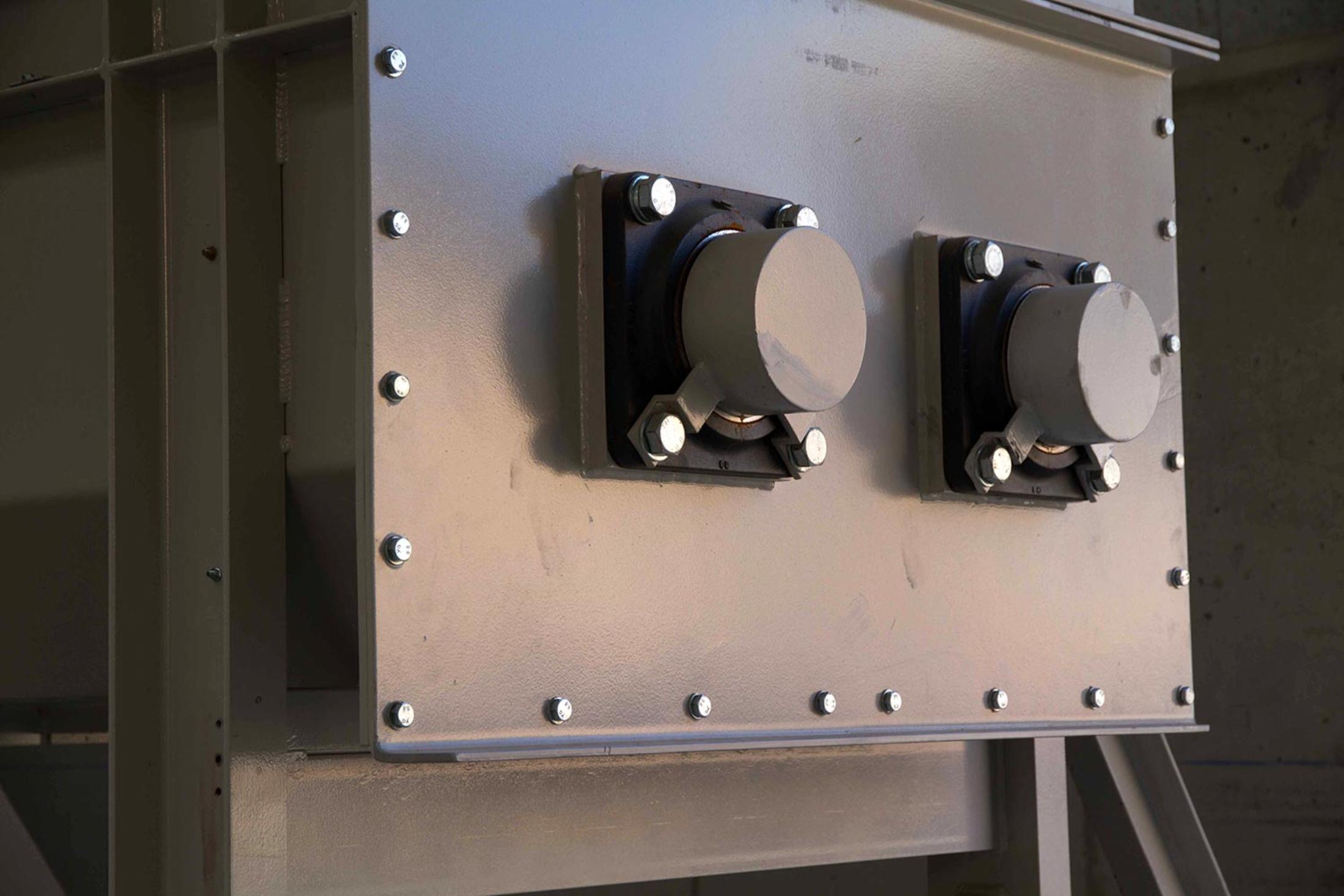
Operational Maintenance
Incorporates strategically placed inspection hatches (key-operated) in the discharge area and external bearings that facilitate wear monitoring and lubrication.
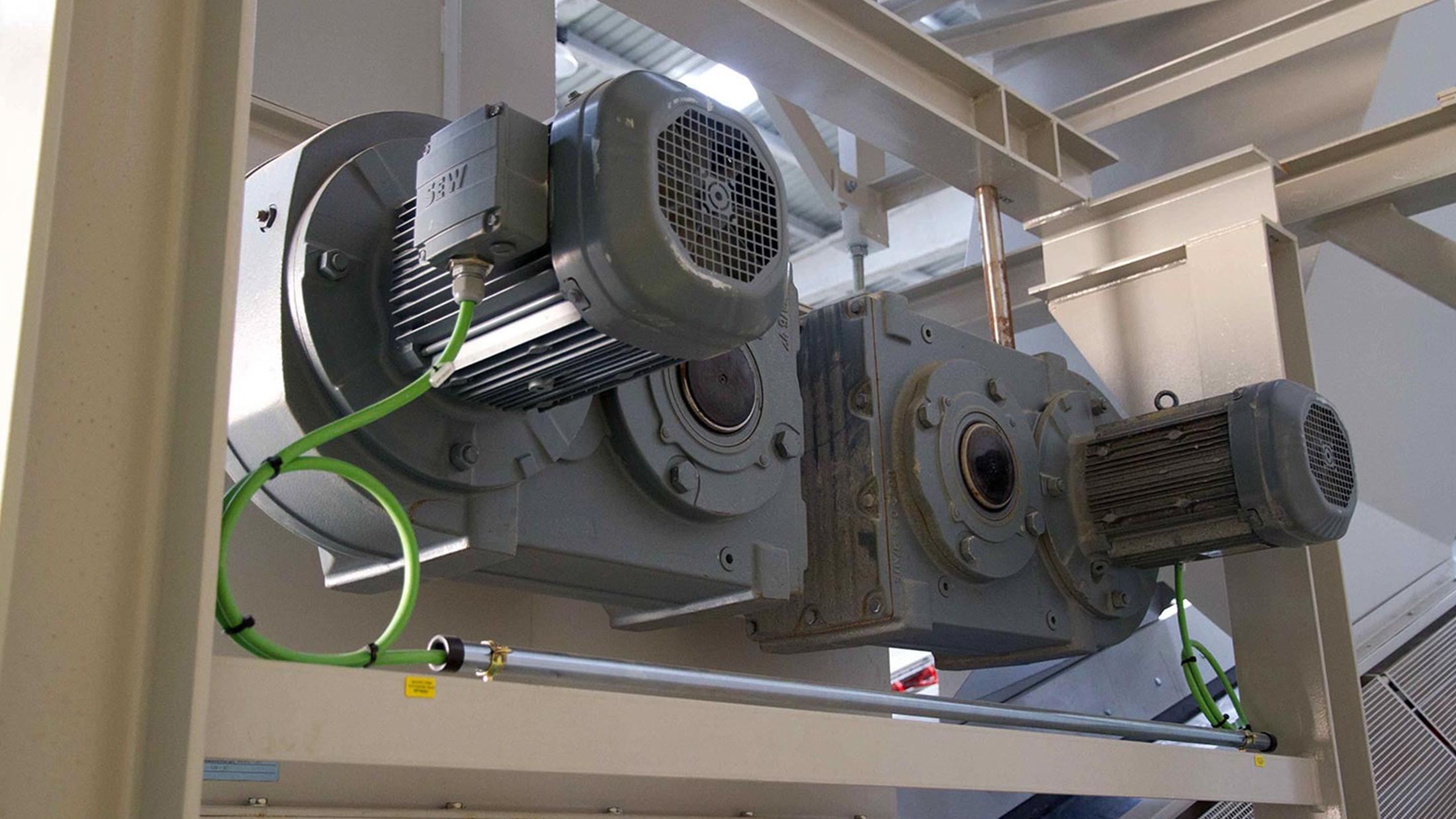
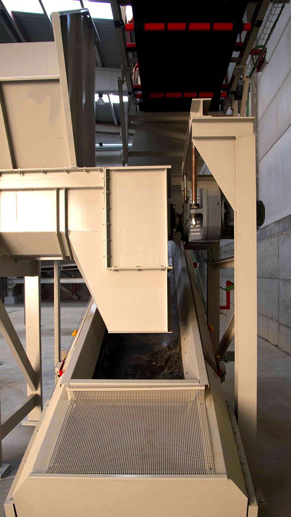
The equipment consists of a highly robust frame built using UPN 160 structural profiles. On this base sits a large-capacity receiving hopper (up to 12 m³) and a 5 mm-thick U-shaped steel trough. Inside, two powerful shafts (auger-type or fitted with paddles) operate, driven by high-performance gearmotors from leading brands such as SEW-Eurodrive. Its compact design ensures maximum stability to withstand the direct, heavy load from wheel loaders or telescopic handlers.

Renting Options
Discover Bianna Renting Services and access Bianna technology without initial investment.
Request a financing studyMain Applications within a Plant
Meter, mix and prepare for transformation
- Flow regulation: uniform feeding to refining trommels or densimetric separators.
- Buffer storage: receiving material from conveyor belts to meter it to the next stage.
- Mixing and conveying: the movement of the screws helps maintain material homogeneity as it moves along.
Aftersales Services
Maintenance, technical service and spare parts. Minimise downtime, maximise results.
Screw Feeder in action

Showroom and training
Bianna Greenways, to see our plants and equipment in real operation
Request a visitTechnical specifications
Receiving hopper
Material entry point for the equipment. Entry occurs at the rear to ensure a constant flow.
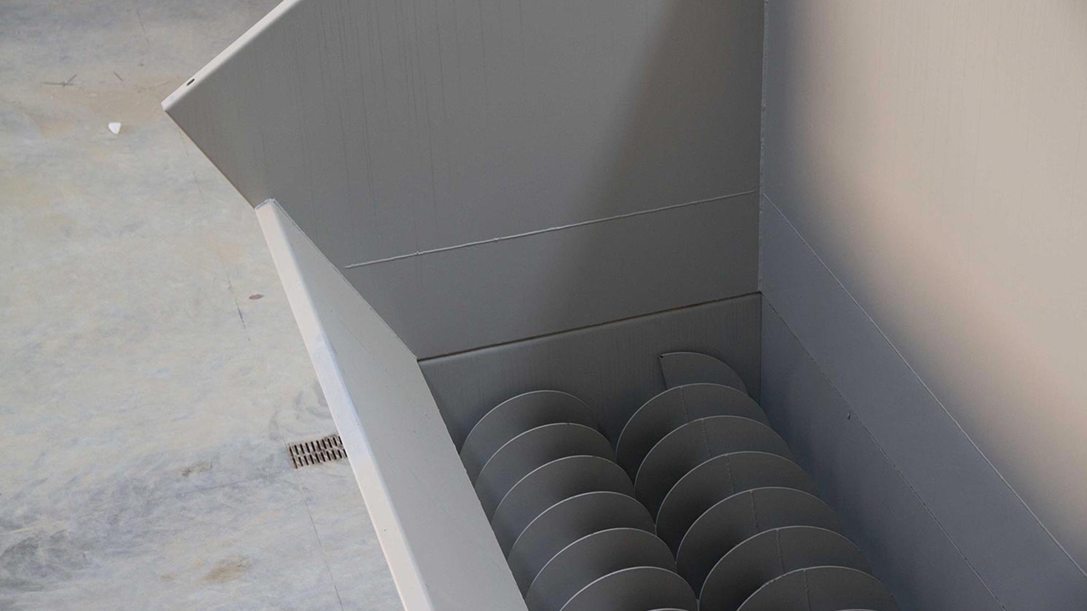
Helical screws
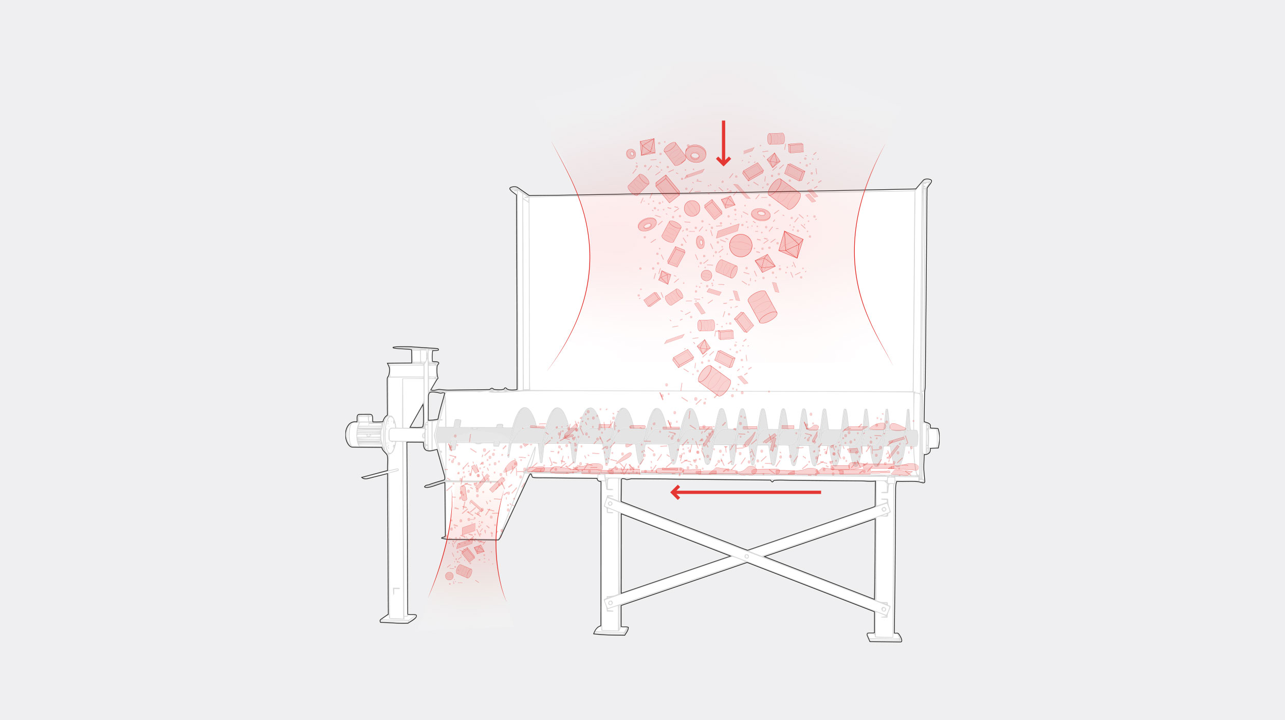
The feeder features two screw shafts with helical screws that allow the material to advance in a continuous and metered manner.
Geared motors
Two geared motors, operating in opposite directions of rotation, provide a rotary movement of the shafts, displacing and mixing the material simultaneously along the trough.
Discharge area
End point of the shafts without screws, causing the material to break apart and fall by gravity.
Trough
Channeling structure where the screw conveyors are housed, guiding the material during its movement towards the discharge point.
Features and components
Operation
Controlled advance for perfect flow
The process begins by depositing the material at the rear of the receiving hopper, preferably with a wheel loader, to ensure the product advances as a uniform block.
As the material advances, it is pulled by the two helical shafts (or paddles) that rotate in opposite directions, pushing the product through the trough at the programmed speed.
To prevent blockages and facilitate discharge, the shafts in the final discharge zone do not include a continuous helix; instead, they feature interspersed welded plates that break up the compacted block, forcing the material to fall freely by gravity onto the next conveyor.